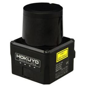
Overview
-> Supply voltage 10 to 30V
-> The smallest and lightest of its kind
-> Measurement distance, 5m
-> Faster response, 66msec
-> More flexible field setting available
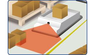
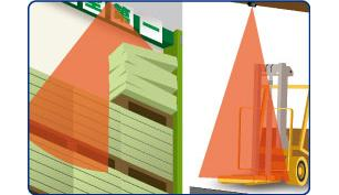
Laser scanning image

SOKUIKI sensor for intelligent robots
Upgraded with wider detection range and faster response time.
More flexible field setting is available,
and even more suitable for obstacle detection of AGVs or load shifting detection.
-> 2D scanner for measuring distance between the sensor and its surroundings.
-> Supply voltage 10 to 30V
-> The smallest and lightest of its kind
-> Measurement distance, 5m
-> Faster response, 66msec
-> More flexible field setting available


| Cân nặng | 130 g |
|---|---|
| Kích thước | 0.5 × 0.5 × 0.7 cm |
| Product name | Scanning Laser Range Finder |
| Model | UST-05LA |
| Supply voltage | DC 12V/DC 24V (operation range 10 to 30V, ripple within 10%) |
| Supply current | 150mA (DC 24V) or less (during start up about 400mA is necessary.) |
| Light source | Laser semiconductor (905nm), Laser class 1(IEC60825-1:2007, Accession number:1420210-000) |
| Detection range and object | 60mm to 5000mm (white Kent sheet) |
| 60mm to 2000mm (diffuse reflectance 10% ) | |
| Minimum detectable size 130mm (changes according to distance)*1 | |
| Accuracy | 60mm to 5000mm ±40mm*2 |
| Standard deviation | σ<20mm*2 |
| Scan angle | 270° |
| Scan speed | 25msec25ms (motor speed 2400rpm) |
| Angular resolution | 0.5° |
| Start up time | Within 10 sec (start up time differs if malfunction is detected during start up) |
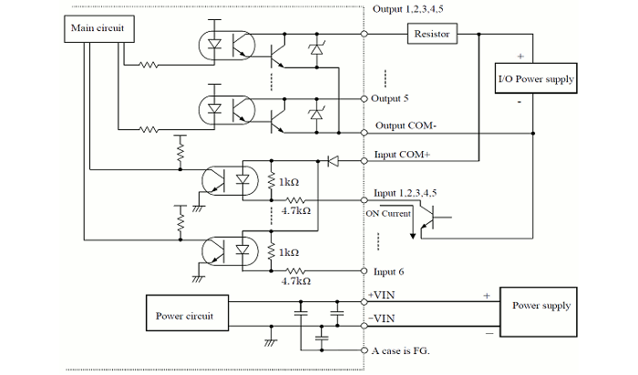
| Outputs | Photo-coupler, open collector output Max DC 30V 50mA Output 1: Output 1 OFF during object detection Output 2: Output 2 OFF during object detection Output 3: Output 3 OFF during object detection Malfunction output: ON during normal operation, OFF during malfunction Synchronization output: Synchronization signal during Master/Slave operation. Note: Output 1 to 3 are switched OFF during malfunction state |
| Inputs | Photo-coupler, common anode, power supply is 4mA when input is ON Input 1 to 5: Area switching inputs (refer Table1) Synchronization input: Input synchronization signal during Slave operation. |
| Output response time*3 | OFF : 66msec to 3241msec ON : 66msec to 3241msec |
| Hysteresis | Hysteresis high (6.25%, not less than 60mm) Hysteresis low (3.125%, not less than 30mm) No Hysteresis (Default) |
| Interface | USB/RS422(UST-05LA only) |
| LED display | Blue LED: ON during normal operation, blink during the start up, Orange LED 1: Output 1 ON during object detection Orange LED 2: Output 2 ON during object detection Orange LED 3: Output 3 ON during object detection |
| Synchronization function | Synchronization Master/Slave operation mode (can set by using Area Designer)*4 Synchronization slave mode (0°) Synchronization slave mode (90°) Synchronization slave mode (180°) Synchronization slave mode (270°) |
| Surrounding intensity | Less than 80,000lx Note : Avoid direct sunlight or other illumination sources as it may cause sensor malfunction |
| Ambient temperature humidity | -10°C to +50°C, below 85%RH (without dew, frost) |
| Storage temperature humidity | -30°C to +70°C, below 85%RH (without dew, frost) |
| Vibration resistance | 10 to 55Hz double amplitude of 1.5mm for 2hrs in each X, Y, and Z direction 55 to 200Hz 98m / s2 sweep of 2min for 1hr in each X,Y and Z direction |
| Shock resistance | 196m/s2 (20G) X,Y and Z direction 10 times. |
| Insulation resistance | 10MΩ, DC 500V |
| Protective structure | IP65 |
| EMC standards | (EMI) EN61326-1:2013 EN55011:2009 + A1:2010 (EMS) EN61326-1:2013 EN61000-4-2:2009 EN61000-4-3:2006 + A1:2008 + A2:2010 EN61000-4-4:2012 EN61000-4-6:2009 EN61000-4-8:2010 |
| Weight | 130g |
| Material | Front case: Polycarbonate, Rear case: Aluminum |
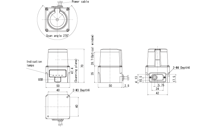
| Dimensions (W×D×H) | 50×50×70mm |
*1. In the case of installing the sensor parallel to the Emitter/Receiver surface. Minimum detectable size of the object can be set by Area Designer.
*2. Under the factory standard testing condition using white Kent sheet.
*3. Initial setting is 66msec. ON/OFF delay function switching is possible by Area Designer. Response time can be further delayed by a maximum of 1scan during the area switching.
*4. Initial setting is synchronization master. When using synchronization operation, refer to section 5.3 for details about synchronization wiring. Synchronization slave setting is possible using Area Designe
| Color | Signal |
| Brown | +VIN(DC12V/DC24V) |
| Blue | -VIN |
| Black | Output 1 |
| White | Output 2 |
| White(Blue) | Output 3 |
| Orange | Malfunction Output |
| Light green | Synchronous Output |
| Gray | COM Output – |
| Red | COM Input + |
| Green | Input 1 |
| Yellow | Input 2 |
| Purple | Input 3 |
| White (Black) | Input 4 |
| White (Red) | Input 5 |
| Light Blue | Synchronous Input |
| Pink | RS422_GND |
| Yellow(Red) | TXD+ |
| Yellow(Black) | TXD- |
| Light Blue(Red) | RXD+ |
| Light Blue(Black) | RXD- |
Note1 : Input/Output direction is mentioned from the sensor`s side.
Note2 : Colors inside the bracket indicates dual color cable.
Note3 : Keep the input wires open or connect to input Com+ if not in use.
Note4 : Keep the output wires open or connect to output Com- if not in use.
| Input1 | Input2 | Input3 | Input4 | Input5 | Area Number |
| ON | ON | ON | ON | ON | Laser off*1 |
| OFF | ON | ON | ON | ON | Area1 |
| ON | OFF | ON | ON | ON | Area2 |
| OFF | OFF | ON | ON | ON | Area3 |
| ON | ON | OFF | ON | ON | Area4 |
| OFF | ON | OFF | ON | ON | Area5 |
| ON | OFF | OFF | ON | ON | Area6 |
| OFF | OFF | OFF | ON | ON | Area7 |
| ON | ON | ON | OFF | ON | Area8 |
| OFF | ON | ON | OFF | ON | Area9 |
| ON | OFF | ON | OFF | ON | Area10 |
| OFF | OFF | ON | OFF | ON | Area11 |
| ON | ON | OFF | OFF | ON | Area12 |
| OFF | ON | OFF | OFF | ON | Area13 |
| ON | OFF | OFF | OFF | ON | Area14 |
| OFF | OFF | OFF | OFF | ON | Area15 |
| ON | ON | ON | ON | OFF | Area16 |
| OFF | ON | ON | ON | OFF | Area17 |
| ON | OFF | ON | ON | OFF | Area18 |
| OFF | OFF | ON | ON | OFF | Area19 |
| ON | ON | OFF | ON | OFF | Area20 |
| OFF | ON | OFF | ON | OFF | Area21 |
| ON | OFF | OFF | ON | OFF | Area22 |
| OFF | OFF | OFF | ON | OFF | Area23 |
| ON | ON | ON | OFF | OFF | Area24 |
| OFF | ON | ON | OFF | OFF | Area25 |
| ON | OFF | ON | OFF | OFF | Area26 |
| OFF | OFF | ON | OFF | OFF | Area27 |
| ON | ON | OFF | OFF | OFF | Area28 |
| OFF | ON | OFF | OFF | OFF | Area29 |
| ON | OFF | OFF | OFF | OFF | Area30 |
| OFF | OFF | OFF | OFF | OFF | Area31 |
*1: Laser is switched off when all inputs(1 to 5) are ON.
 Hokuyo chuyên sản xuất các thiết bị quang học như máy đo khoảng cách laser, thiết bị truyền dữ liệu quang học, cảm biến ảnh, bộ đếm tự động và cửa tự động mang lại hiệu suất và độ tin cậy cao.