DMS-G/H-V

Nhận báo giá

The Optical Data Transmission Device to meet the needs of compactness and lightness.

Body size 50x50x20mm is only half of our previous model DM series.

Weight 210g is much lighter than before.

Features

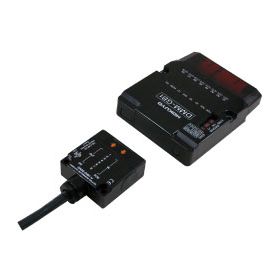
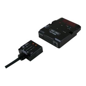
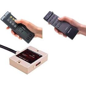
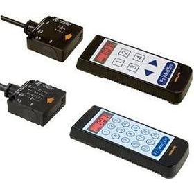
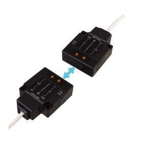
This is Optical Data Transmission Device (Parallel I/O) suitable for such as interlocking with carrier robots, indicating destination of AGVs.

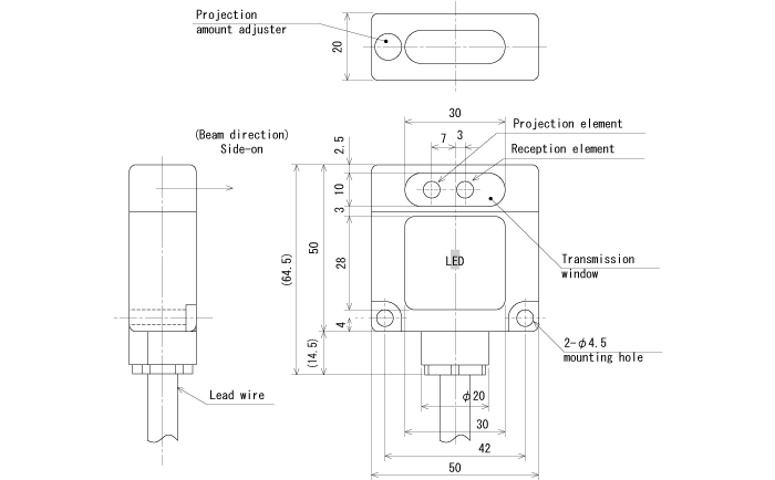
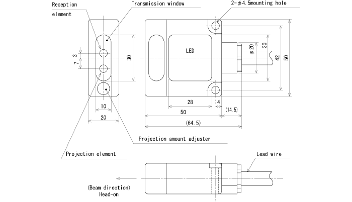
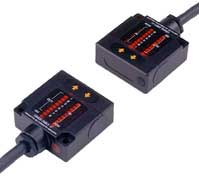
*This is small size and right weight with 50*50*20mm.
*This device provides light-projecting amount adjuster, and it can adjust the communicating range by it.

Easy friendly to control with parallel signals

Easy friendly to control with parallel signals

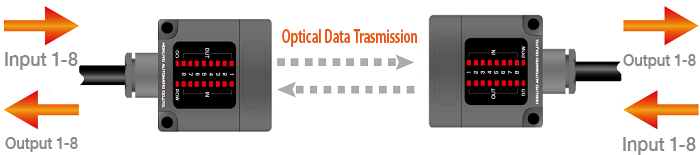
This products have parallel signals of maximum 8 points each for input and output, it does not require difficult signal processing.

Communicable with wireless between AGVs and Stations

Communicable with wireless between AGVs and Stations

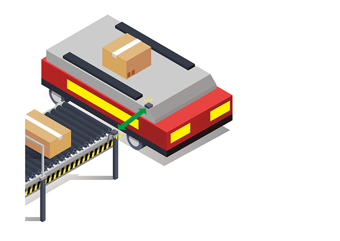
This performs transmission using optical light, so it is possible to communicate wirelessly with mobile vehicles that are hard to lay cables. It can be used for communication to between the stations and mobile vehicles like AGVs to instruct the destination where the vehicles should go.

2 types of optical axis direction selectable based on the installation way

2 types of optical axis direction selectable based on the installation way

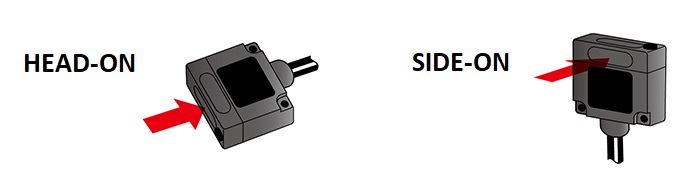
2 types of HEAD-ON and SIDE-ON are lined up.

Model No.

Model

Model numberCode numberDirectional mountingTransmission distanceSignals
DMS-GA1-VWDMS006Head-on1m4-bit
DMS-GA2-VWDMS0153m
DMS-GB1-VWDMS0041m8-bit
DMS-GB2-VWDMS0133m
DMS-HA1-VWDMS007Side-on1m4-bit
DMS-HA2-VWDMS0163m
DMS-HB1-VWDMS0051m8-bit

Specifications

Specification

TypeParallel type
4-bit type8-bit type
Model No.DMS-
GA1-V
DMS-
GA2-V
DMS-
HA1-V
DMS-
HA2-V
DMS-
GB1-V
DMS-
GB2-V
DMS-
HB1-V
DMS-
HB2-V
Directional mountingHead-onSide-onHead-onSide-on
Transmission distance0 to 1m0 to 3m0 to 1m0 to 3m0 to 1m0 to 3m0 to 1m0 to 3m
Directional angle (Full angle)30°10°30°10°30°10°30°10°
Transmission methodHalf-duplex two-way transmission
Transmission time40msec or less
Modulation methodPulse modulation
Detection methodParity check
Power source24VDC(10 to 30VDC)
InputContact or open-collector(ON current 2.5mA or more,
OFF current 1mA or less, Operating threshold current 1.5 to 2mA)
OutputNPN open-collector(30VDC, 50mA or less, Residual voltage 1.8V or less)
Current consumption100mA Max.
Ambient illuminance4,000lux or less(Incandescent lamp)
Ambient temperature/humidity-10 to +50° C, 85%RH or less
Impact resistance500m/s2, each 10 time in X, Y and Z directions
ConnectionLead wire 2m long
Protective structureIP64(IEC standard)

DMS-GA1-C/HA1-C which can be communicated with old type, DM-GA1/HA1 are lined-up.

External dimension

External dimension

DMS-HA1-V/HA2-V, DMS-HB1-V/HB2-V(SIDE-ON type)

DMS-HA1-V/HA2-V, DMS-HB1-V/HB2-V(SIDE-ON type)

DMS-GA1-V/GA2-V, DMS-GB1-V/GB2-V(HEAD-ON type)

DMS-GA1-V/GA2-V, DMS-GB1-V/GB2-V(HEAD-ON type)

I/O circuit

I/O Circuit

Input

Input
ON current 2.5mA or more,
OFF current 1mA or less,
Note) Don’t use the sensor with 2-wire.
Operating threshold current 1.5 to 2mA

Output

Output
NPN open-collector output 30VDC 50mA Residual voltage 1.8V or less

Input/ output circuit

Input/ output circuit

Connection

Connection
DMS-GA1-V/GA2-V, DMS-HA1-V/HA2-V(4-bit type)

ColorsPin No.Functions
Black1IN1
Brown2IN2
Red3IN3
Orange4IN4
White/yellow5MODE*1
Yellow6SELECT*2
White/blue7NC
Green8OUT1
Blue9OUT2
Purple10OUT3
Gray11OUT4
White12GO*3
Yellow/green13COM(0V)
Yellow/red14+VIN
Yellow/black15-VIN(0V)
ShieldShield

Connection

Connection
DMS-GB1-V/GB2-V, DMS-HB1-V/HB2-V(8-bit type)

Connector (1) Connector (2)
ColorsPin No.FunctionsColorsPin No.Functions
Pale blue1COM(0V)Green1IN5
Pink2MODE*1Green/black2OUT5
White3SELECT*2Blue3IN6
White/black4GO*3Blue/black4OUT6
Brown5IN1Purple5IN7
Brown/black6OUT1Purple/black6OUT7
Red7IN2Gray7IN8
Red/black8OUT2Gray/black8OUT8
Orange9IN3Pink/black9+VIN
Orange/black10OUT3Pale blue / black10-VIN
Yellow11IN4ShieldShield
Yellow/black12OUT4 

*1 MODE input
This is to choose transmission/reception mode when standing by
*Transmission stand-by mode by opened between mode and I/O COM
*Reception stand-by mode by short-circuited between mode and I/O COM
*2 SELECT input
This is to stop transmission/reception optionally by outer signal
*Operating by opened between select and I/O COM
*Stopping by short-circuited between select and I/O COM
*3 GO output
This is to check correct optical single
*ON when receiving correct optical axis
*OFF when interrupting optical axis(Not-receiving)
Note) Cable ends for unused input/output, GO output, SELECT input, MODE input, NC(4-bit type) should be processed individually and don’t connect with other cable.
It may cause unstable operation if package processing.
Note) Don’t use the connector attached to the cables as connecting terminal.
Note) If one side is set to transmission stand-by mode, other one should be set to reception standby mode.

Caution
I/O direction is appeared in accordance with DMS.

Thương Hiệu

hokuyo_logo

hokuyo banner Hokuyo chuyên sản xuất các thiết bị quang học như máy đo khoảng cách laser, thiết bị truyền dữ liệu quang học, cảm biến ảnh, bộ đếm tự động và cửa tự động mang lại hiệu suất và độ tin cậy cao.