🔥🔥🔥 Bộ phận CSKH của chúng tôi sẽ giúp bạn lựa chọn và mua sản phẩm hoặc linh kiện phù hợp, ngay sau khi bạn gửi yêu cầu. Hãy nhận bảng báo giá và thời gian giao hàng ngay qua hotline 0903757278. Giá trên website là giá bán lẻ, liên hệ để có giá tốt nhất cho dự án !!!
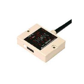
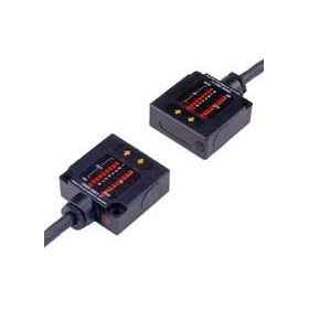
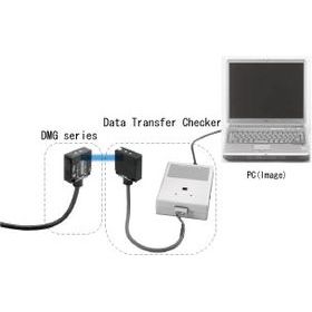
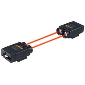
-> This device is smaller size and lighter weight than old type. -> This device provides light-projecting amount adjuster and so it is easy to adjust the communication distance.
Specifications
Specifications
Type
Parallel type
16-bit type
Model No.
DMH-GC1
DMH-HC1
Transmission capacity(I/O)
16BIT/16BIT
Direction
HEAD-ON
SIDE-ON
Transmission distance
0 to 3m(can be adjusted by adjuster)
Directional angle
±13°
Transmission method
Half-duplex two-way transmission
Transmission time
15ms
Modulation method
FSK modulation
Detection method
Bit-reverse comparison system
Power source
DC18 to 30V(ripple 10% or less)
Current consumption
150mA Max.
Ambient illuminance
10,000lux or less
Ambient temperature/humidity
-10 to +50 degrees C, 85%RH or less
Vibration resistance
Double amplitude 1.5mm, 10 to 55Hz, each 2 hour in X, Y and Z directions
Impact resistance
500m/s2, each 10 time in X, Y and Z directions
Connection
Lead wire (0.2mm2, 40 cores, shield cable 2m long)
Protective structure
IP64(IEC standard)
Weight
Approx. 400g(including the cable 2m)
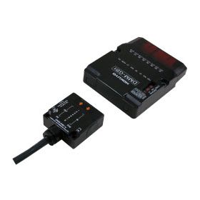
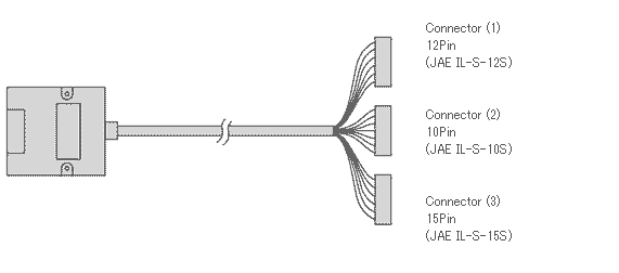
D-sub connector type and long distance type(15m) are lined-up.
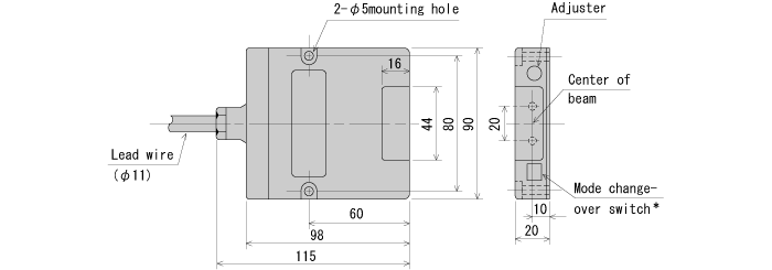
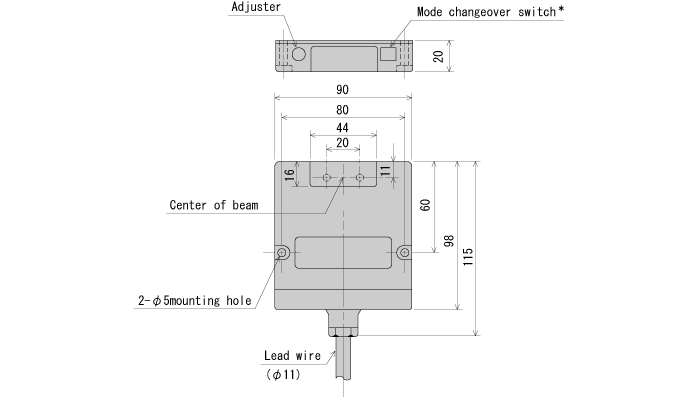
External dimension
External dimension
DMH-GC1(HEAD-ON type)
DMH-HC1(SIDE-ON type)
* Mode changeover switch : If one is set to T side(transmission priority mode), other one have to be set to R side(reception priority mode).
I/O circuit
I/O Circuit
Input
Flow current when ON(IO) : approx. 5mA(when 24VDC) ON voltage : 2V or less, OFF voltage : 8V or more
Output
NPN open-collector output 35DC 50mA residual voltage 0.9V or less
Connection
Connector (1)
Connector (2)
Colors
Pin No.
Functions
Colors
Pin No.
Functions
Pink(red 1)
1
Power +V
White(Black 1)
1
OUT11
Pink(red 2)
2
Power -V(COM)
White(Black 2)
2
IN11
Pink(red 3)
3
OUT16
White(Black 3)
3
OUT10
Pink(red 4)
4
IN16
Gray(red 1)
4
IN10
Pink(black 1)
5
OUT15
Gray(red 2)
5
IN9
Pink(black 2)
6
IN15
Gray(red 3)
6
OUT9
Pink(black 3)
7
OUT14
Gray(red 4)
7
IN8
Pink(black 4)
8
IN14
Gray(black 1)
8
OUT8
White(red 1)
9
OUT13
Gray(black 2)
9
IN7
White(red 2)
10
IN13
Gray(black 3)
10
OUT7
White(red 3)
11
OUT12
White(red 4)
12
IN12
Connector (3)
Colors
Pin No.
Functions
Orange(red 1)
1
IN6
Orange(red 2)
2
OUT6
Orange(red 3)
3
IN5
Orange(red 4)
4
OUT5
Orange(black 1)
5
IN4
Orange(black 2)
6
OUT4
Orange(black 3)
7
IN3
Orange(black 4)
8
OUT3
Yellow(red 1)
9
IN2
Yellow(red 2)
10
OUT2
Yellow(red 3)
11
IN1
Yellow(red 4)
12
OUT1
Yellow(black 1)
13
SELECT*1
Yellow(black 2)
14
GO*2
Yellow(black 3)
15
STROBE*3
Note) Don’t use White(black4), gray(black4) and Yellow(black4). If cable is cut on the way, cut it at the base. Note) Don’t use the connector attached to the cables as connecting terminal.
*1 SELECT input This is to stop transmission/reception optionally by outer signal *Operating by opened between select and I/O COM *Stopping by short-circuited between select and I/O COM
*2 GO output This is to check correct optical single *ON when receiving correct optical axis *OFF when interrupting optical axis(Not-receiving)