
Overview
-> It is 5 times faster than DMS series and this device can communicate more data in specific time.
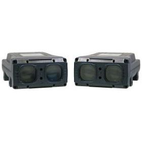
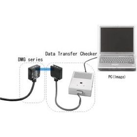
This device is high-speed type, data transmission device.
The transmission time is 7ms which is 5 times faster than the normal 8-bit DM series.
So it’s possible to transfer and receive more data within limited time.
| Type | Parallel type | |||
| 8-bit type | ||||
| Model No. | DMH-GB1 | DMH-GB2 | DMH-HB1 | DMH-HB2 |
| Transmission capacity(I/O) | 8BIT/8BIT | |||
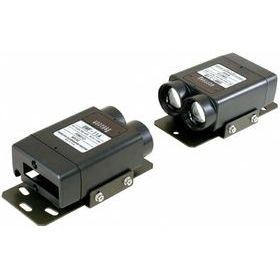
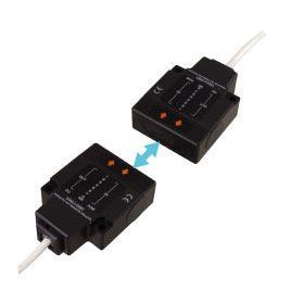
| Direction | HEAD-ON | SIDE-ON | ||
| Transmission distance | 0.6m | 3m | 0.6m | 3m |
| Directional angle | ±15° | ±5° | ±15° | ±5° |
| Transmission method | Half-duplex two-way transmission | |||
| Transmission time | 7msec | |||
| Modulation method | FSK modulation | |||
| Detection method | Bit-reverse comparison system | |||
| Power source | 18 to 30VDC(ripple 10% or less) | |||
| Current consumption | 100mA Max. | |||
| Ambient illuminance | 10,000lux or less | |||
| Ambient temperature/ humidity | -10 to +50 degrees C, 85%RH or less | |||
| Vibration resistance | Double amplitude 1.5mm, 10 to 30Hz, each 2 hour in X, Y and Z directions | |||
| Impact resistance | 500m/s2, each 10 time in X, Y and Z directions | |||
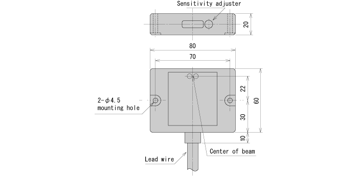
| Connection | Lead wire (0.2mm2, 23 cores, shield cable 2m long) | |||
| Protective structure | IP64(IEC standard) | |||

| Connector (1) | Connector (2) | |||||
| Colors | Pin No. | Functions | Colors | Pin No. | Functions | |
| Pale blue | 1 | Power 0V | Green / black | 1 | GO*3 | |
| Pink | 2 | Power +V | Blue | 2 | STROBE*4 | |
| White | 3 | IN1 | – | 3 | – | |
| White / black | 4 | IN2 | Purple | 4 | OUT8 | |
| Brown | 5 | IN3 | Purple / black | 5 | OUT7 | |
| Brown / black | 6 | IN4 | Gray | 6 | OUT6 | |
| Red | 7 | IN5 | Gray / black | 7 | OUT5 | |
| Red / black | 8 | IN6 | Pink / black | 8 | OUT4 | |
| Orange | 9 | IN7 | Pale blue / black | 9 | OUT3 | |
| Orange / black | 10 | IN8 | Pink/red | 10 | OUT2 | |
| Yellow | 11 | MODE*1 | Yellow/red | 11 | OUT1 | |
| Yellow / black | 12 | COM(0V) | – | 12 | – | |
| Green | 13 | SELECT*2 | – | 13 | – | |
| Shield | Shield | |||||
*1 MODE input
This is to choose transmission/reception mode when standing by
*Transmission stand-by mode by opened between mode and I/O COM
*Reception stand-by mode by short-circuited between mode and I/O COM
Note) If one side is set to transmission stand-by mode, other one should be set to reception standby mode.
*2 SELECT input
This is to stop transmission/reception optionally by outer signal
*Operating by opened between select and I/O COM
*Stopping by short-circuited between select and I/O COM
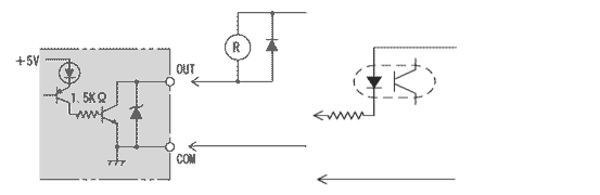
*3 GO output
This is to check correct optical single
*ON when receiving correct optical axis
*OFF when interrupting optical axis(Not-receiving)
*4 Strobe
It is getting ON when data is fixed.
Note) The connector attached can’t be used as relay terminal.