Overview
Features
->This is compatible with SEMI standards
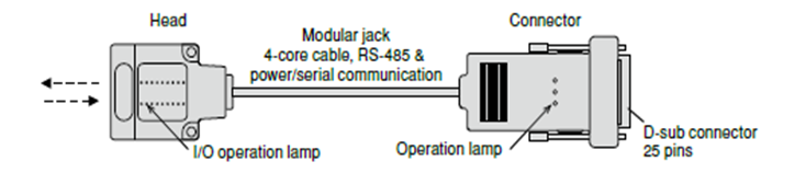
->Modular cable is applied between a head and a connector of E84 parallel I/O and it is easy to make a wiring
->This device has logging function (up to 100 times data changes)

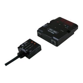
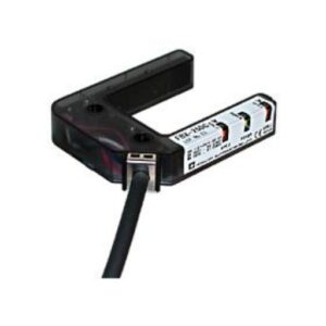
This is Parallel I/O (8-bit) with RJ-11 modular cable type.
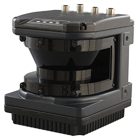
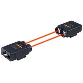
It communicates wirelessly (infrared ray) between mobile vehicles sides such as AGVs (Automated Guided Vehicles) and the station sides by using this.
This is provided with a logging function and corresponded to SEMI E84.
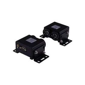
This composes of Head, Connector and RJ-11 cable, it is user friendly to make wiring.
->This is compatible with SEMI standards
->Modular cable is applied between a head and a connector of E84 parallel I/O and it is easy to make a wiring
->This device has logging function (up to 100 times data changes)
| Model No. | Part No. | Direction | Transmission distance |
| DMJ-GB1 | WDMJ003 | Head-ON | 1m |
| DMJ-HB1 | WDMJ004 | Side-ON |
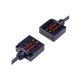
●Connector
| Model No. | Part No. | Mode | Fixed screw |
| DMJ-CN1 | WDMJ005 | Changeover of transmission/reception standby mode by outer input | Metric screw (M2.6) |
| DMJ-CN2 | WDMJ006 | Changeover of transmission/reception standby mode by outer input | Inch screw (#4-40UNC) |
| DMJ-CN3 | WDMJ007 | Reception standby mode (Fixed) | Metric screw (M2.6) |
| DMJ-CN4 | WDMJ008 | Reception standby mode (Fixed) | Inch screw (#4-40UNC) |
SEMI E84 compatible products list *1
| Model No. | Part No. | Direction | Cable length | SEMI E84 standard/ D-sub 25pin connector *3 | Mode *2 | Logging data *4 | Remarks |
| DMJ-GB1 (Sensor) | WDMJ003 | Head-ON | - | - | - | 100 times | - |
| DMJ-HB1 (Sensor) | WDMJ004 | Side-ON | - | - | - | 100 times | - |
| DMJ-CN1 (Connector) | WDMJ005 | - | - | Provided (Metric screw) | Changeover of transmission/ reception standby | - | - |
| DMJ-CN2 (Connector) | WDMJ006 | - | - | Provided (Inch screw) | Changeover of transmission/ reception standby | - | - |
| DMJ-CN3 (Connector) | WDMJ007 | - | - | Provided (Metric screw) | Reception standby | - | - |
| DMJ-CN4 (Connector) | WDMJ008 | - | - | Provided (Inch screw) | Reception standby | - | - |
| DMJ-GB1-Z01 (Sensor) | WDMJ010 | Head-ON | - | - | - | 100 times | High-frequency noise resistance |
| DMJ-HB1-Z01 (Sensor) | WDMJ011 | Side-ON | - | - | - | 100 times | High-frequency noise resistance |
| DMJ-CN3-Z01 (Connector) | WDMJ013 | - | - | Provided (Metric screw) | Reception standby | - | High-frequency noise resistance |
| DMJ-CN4-Z01 (Connector) | WDMJ014 | - | - | Provided (Inch screw) | Reception standby | - | High-frequency noise resistance |
| DMJ-HB1-Z50 (Sensor) | WDMJ015 | Side-ON | - | - | - | 1600 times | Ambient light resistance |
| DMJ-GB1-Z50 (Sensor) | WDMJ020 | Head-ON | - | - | - | 1600 times | Ambient light resistance |
| DMJ-CN3-Z50 (Connector) | WDMJ016 | - | - | Provided (Metric screw) | Reception standby | - | Ambient light resistance |
| DMJ-CN4-Z50 (Connector) | WDMJ017 | - | - | Provided (Inch screw) | Reception standby | - | Ambient light resistance |
| Modular cable (White) | WZ00033 | - | 5m | - | - | - | RJ-11 connector at both ends |
| Modular cable (Black) | WZ00043 | - | 5m | - | - | - | RJ-11 connector at both ends |
*1 Product specifications other than those listed are the same as standard products, so please refer to the product specifications page.
*2 It may be necessary to notify the model to be adopted in advance.
*3 The pin assignment is compliant with SEMI E84. There are two types of fixing screws, metric screws and inch screws. Devices that support SEMI E84-0699, -0999 may use metric screws. Inch screws are specified for SEMI E84-0200A and later versions.
*4 Recommended product. The logging function is effective in investigating the cause when a transfer problem occurs. Since the log data can be easily sent by attaching it to an e-mail, it is possible to immediately analyze the defect phenomenon in-house even in the case of troubles with overseas users.
| Model No. | DMJ-GB1(WDMJ003) | DMJ-HB1(WDMJ004) | |||
| Direction | HEAD-ON | SIDE-ON |
Connector
| Model No. | DMJ-CN1 (WDMJ005) | DMJ-CN2 (WDMJ006) | DMJ-CN3 (WDMJ007) | DMJ-CN4 (WDMJ008) | |
| Transmission method | Changeover of transmission/reception standby mode by outer input | Changeover of transmission/reception standby mode by outer input | Reception standby mode(Fixed) | Reception standby mode(Fixed) | |
| Fixed screw | Metric screw (M2.6) | Inch screw (#4-40UNC) | Metric screw (M2.6) | Inch screw (#4-40UNC) | |
| Power source | DC24V | ||||
| Current consumption | 100mA Max. | ||||
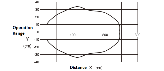
| Transmission distance | 1.0m (can be adjusted by adjuster) | ||||
| Directional angle | 30 degree (Full angle) | ||||
| Transmission capacity(I/O) | 8-bit/8-bit | ||||
| Transmission method | Half-duplex two-way transmission | ||||
| Transmission time | 45ms | ||||
| Modulating system | Pulse modulation | ||||
| Detecting system | Parity check, All output is getting OFF when twice continuous error | ||||
| Specifications between a head and a connector | Communicating standard | RS-485 | |||
| Communicating speed | 38.4kbps | ||||
| Detecting system | Parity check/SUM check | ||||
| Connection | RJ-11(Modular jack) Max.extending length 200m | ||||
| Logging data | Data variable time | Max.100 times *1 | |||
| Memorizing data | Transmitting/Receiving data: Each 8bits, GO output, SELECT input | ||||
| Measuring unit of invariable time | 0.05s | ||||
| Measuring error of invariable time | ±0.05s | ||||
| Measuring range of invariable time | Max.1638.35s (Approx.27min.) *2 | ||||
| Memorizing media | Ferroelectric memory (512 bytes) | ||||
| Memorizing cycle | Min.20msec | ||||
| Memorizing life | Nos.1010times, 10 years | ||||
| Operating lamps | Head | Each parallel I/O is shown. I/O is the same indication as standard device(8-bit type) IN: 8 points, OUT: 8 points, GO, POW, NS NS: Lights up when serial communication with connector is normal. | |||
| Connector | NS:Lights up when serial communication with head is normal. MODE:Lights up when reception-standby mode POW:Lights up when putting power source in | ||||
| Ambient illuminance | 4,000lx or less | ||||
| Ambient temprature/humidity | -10 to 50 degC / 85%RH or less (Not freezing) | ||||
| Vibration resistance | Double amplitude 1.5mm, 10 to 55 Hz, Each 2 hour in X,Y and Z directions | ||||
| Impact resistance | 500m/s2 Each 10 time in X,Y and Z directions | ||||
| Connection | D-sub 25 pins connector | ||||
| Protective structure | IP40 | ||||
| Case | Polycarbonate | ||||
| Weight | Head:Approx.50g, Connector:Approx.70g | ||||
*1 In case that data variable Nos. exceed max. value, it is overwritten from older data.
*2 In case that measuring of invariable data for transmitting/receiving data exceeds max. value, it is memorized as max. value.
Connection cable WZ00033 (cable length 5 m) is available as an option.
Special products (DMJ-G / H-Z series) compatible with SEMI E84 are listed on the model line-up page.
.PNG)
.PNG)
DMJ.PNG)
DMJ.PNG)
| Pin No. | Functions | Specifications | Pin No. | Functions | Specifications |
| 1 | IN1 | Input data | 14 | OUT1 | Output data |
| 2 | IN2 | 15 | OUT2 | ||
| 3 | IN3 | 16 | OUT3 | ||
| 4 | IN4 | 17 | OUT4 | ||
| 5 | IN5 | 18 | OUT5 | ||
| 6 | IN6 | 19 | OUT6 | ||
| 7 | IN7 | 20 | OUT7 | ||
| 8 | IN8 | 21 | OUT8 | ||
| 9 | NC. | ― | 22*1 | +VIN | Power (24VDC±10%) |
| 10 | SELECT | When shorted to COM(No.25) : Stop to communicate When opened : Communication is available | 23*1 | +VIN | |
| 11 | MODE*3 | When shorted to COM (No.25) : Reception standby mode When opened : Transmittion standby mode | 24*2 | -VIN | Power (0V) |
| 12 | GO | ON : Normal data reception OFF : Interrupting the light | 25*2 | COM | COM Common for I/O |
| 13 | NC. | ― |
*1 It is short-circuited between No.22 and No.23.
*2 It is short-circuited between -VIN(No.24) and COM (No.25) inside.
*3 MODE is available only for DMJ-CN1 and DMJ-CN2.