
Overview
-> Supply voltage 10 to 30V
-> The smallest and lightest of its kind
-> Measurement distance, 5m
-> Faster response, 66msec
-> More flexible field setting available
Laser scanning image

More compact and more performant SOKUIKI sensor for intelligent robots
-> 2D scanner for measuring distance between the sensor and its surroundings.
-> Supply voltage 10 to 30V
-> The smallest and lightest of its kind
-> Measurement distance, 5m
-> Faster response, 66msec
-> More flexible field setting available
NPN type: UST-05LN
PNP type: UST-05LNP
two types are available


| Cân nặng | 130 g |
|---|---|
| Kích thước | 50 × 70 cm |


| Product name | Scanning Laser Range Finder |
| Model | UST-05LN |
| Supply voltage | DC 12V/DC 24V (operation range 10 to 30V, ripple within 10%) |
| Supply current | 150mA (DC 24V) or less (during start up about 400mA is necessary.) |
| Light source | Laser semiconductor (905nm), Laser class 1(IEC60825-1:2007, Accession number:1420210-000) |
| Detection range and object | 60mm to 5000mm (white Kent sheet) |
| 60mm to 2000mm (diffuse reflectance 10% ) | |
| Minimum detectable size 130mm (changes according to distance)*1 | |
| Accuracy | 60mm to 5000mm ±40mm*2 |
| Standard deviation | σ<20mm*2 |
| Scan angle | 270° |
| Scan speed | 25msec (motor speed 2400rpm) |
| Angular resolution | 0.5° |
| Start up time | Within 10 sec (start up time differs if malfunction is detected during start up) |
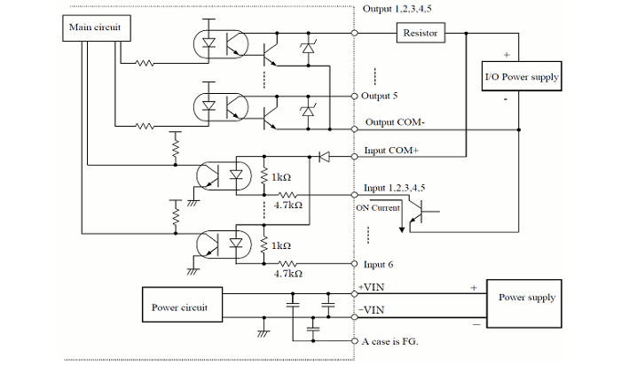
| Outputs | Photo-coupler, open collector output Max DC 30V 50mA Output 1: Output 1 OFF during object detection Output 2: Output 2 OFF during object detection Output 3: Output 3 OFF during object detection Malfunction output: ON during normal operation, OFF during malfunction Synchronization output: Synchronization signal during Master/Slave operation. Note: Output 1 to 3 are switched OFF during malfunction state |
| Inputs | Photo-coupler, common anode, power supply is 4mA when input is ON Input 1 to 5: Area switching inputs (refer Table1) Synchronization input: Input synchronization signal during Slave operation. |
| Output response time*3 | OFF : 66msec to 3241msec ON : 66msec to 3241msec |
| Hysteresis | Hysteresis high (6.25%, not less than 60mm) Hysteresis low (3.125%, not less than 30mm) No Hysteresis (Default) |
| Interface | USB |
| LED display | Blue LED: ON during normal operation, blink during the start up, Output 1 LED(Orange): ON during object detection Output 2 LED(Orange): ON during object detection Output 13LED(Orange): ON during object detection |
| Synchronization function | Master/Slave Synchronization mode is set using the configuration software*4 Slave synchronization mode (0°) Slave synchronization mode (90°) Slave synchronization mode (180°) Slave synchronization mode (270°) |
| Ambient illumination | Less than 80,000lx Note : Avoid direct sunlight or other illumination sources as it may cause sensor malfunction |
| Ambient temperature and humidity | -10°C to +50°C, below 85%RH (without dew, frost) |
| Storage temperature and humidity | -30°C to +70°C, below 85%RH (without dew, frost) |
| Vibration resistance | 10 to 55Hz double amplitude of 1.5mm for 2hrs in each X, Y, and Z direction 55 to 200Hz 98m / s2 sweep of 2min for 1hr in each X,Y and Z direction |
| Shock resistance | 196m/s2 (20G) each X,Y and Z direction 10 times. |
| Insulation resistance | 10MΩ, DC 500V |
| Protective structure | IP65 |
| EMC standards | (EMI) EN61326-1:2013 EN55011:2009 + A1:2010 (EMS) EN61326-1:2013 EN61000-4-2:2009 EN61000-4-3:2006 + A1:2008 + A2:2010 EN61000-4-4:2012 EN61000-4-6:2009 EN61000-4-8:2010 |
| Weight | 130g |
| Material | Upper case: Polycarbonate, Lower case: Aluminum |
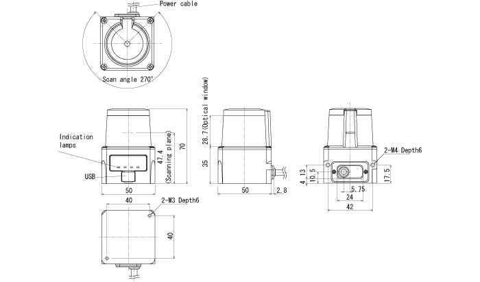
| Dimensions (W×D×H) | 50×50×70mm |
*1. In the case of installing the sensor parallel to the Emitter/Receiver surface. Minimum detectable size of the object can be set by Area Designer.
*2. Under the factory standard testing condition using white Kent sheet.
*3. Initial setting is 66msec. ON/OFF delay function switching is possible by Area Designer. Response time can be further delayed by a maximum of 1scan during the area switching.
*4. Initial setting is synchronization master. Synchronization slave setting is possible using Area Designer


| Color | Signal |
| Brown | +VIN(DC12V/DC24V) |
| Blue | -VIN |
| Black | Output 1 |
| White | Output 2 |
| White(Blue) | Output 3 |
| Orange | Malfunction Output |
| Light green | Synchronous Output |
| Gray | COM Output – |
| Red | COM Input + |
| Green | Input 1 |
| Yellow | Input 2 |
| Purple | Input 3 |
| White (Black) | Input 4 |
| White (Red) | Input 5 |
| Light Blue | Synchronous Input |
| Pink | Non Connect |
| Yellow(Red) | Non Connect |
| Yellow(Black) | Non Connect |
| Light Blue(Red) | Non Connect |
| Light Blue(Black) | Non Connect |
Note1 : Input/Output direction is mentioned from the sensor`s side.
Note2 : Colors inside the bracket indicates dual color cable.
Note3 : Keep the input wires open or connect to input Com+ if not in use.
Note4 : Keep the output wires open or connect to output Com- if not in use.
| Input1 | Input2 | Input3 | Input4 | Input5 | Area Number |
| ON | ON | ON | ON | ON | Laser off*1 |
| OFF | ON | ON | ON | ON | Area1 |
| ON | OFF | ON | ON | ON | Area2 |
| OFF | OFF | ON | ON | ON | Area3 |
| ON | ON | OFF | ON | ON | Area4 |
| OFF | ON | OFF | ON | ON | Area5 |
| ON | OFF | OFF | ON | ON | Area6 |
| OFF | OFF | OFF | ON | ON | Area7 |
| ON | ON | ON | OFF | ON | Area8 |
| OFF | ON | ON | OFF | ON | Area9 |
| ON | OFF | ON | OFF | ON | Area10 |
| OFF | OFF | ON | OFF | ON | Area11 |
| ON | ON | OFF | OFF | ON | Area12 |
| OFF | ON | OFF | OFF | ON | Area13 |
| ON | OFF | OFF | OFF | ON | Area14 |
| OFF | OFF | OFF | OFF | ON | Area15 |
| ON | ON | ON | ON | OFF | Area16 |
| OFF | ON | ON | ON | OFF | Area17 |
| ON | OFF | ON | ON | OFF | Area18 |
| OFF | OFF | ON | ON | OFF | Area19 |
| ON | ON | OFF | ON | OFF | Area20 |
| OFF | ON | OFF | ON | OFF | Area21 |
| ON | OFF | OFF | ON | OFF | Area22 |
| OFF | OFF | OFF | ON | OFF | Area23 |
| ON | ON | ON | OFF | OFF | Area24 |
| OFF | ON | ON | OFF | OFF | Area25 |
| ON | OFF | ON | OFF | OFF | Area26 |
| OFF | OFF | ON | OFF | OFF | Area27 |
| ON | ON | OFF | OFF | OFF | Area28 |
| OFF | ON | OFF | OFF | OFF | Area29 |
| ON | OFF | OFF | OFF | OFF | Area30 |
| OFF | OFF | OFF | OFF | OFF | Area31 |
*1: Laser is switched off when all inputs(1 to 5) are ON.